An FIR filter design was selected for this pre-processing filter ASIC. FIR filters
have several advantages, including a linear phase shift with frequency, and limited
overall distortion. An N-tap FIR
is defined by its coefficients h[], pre-processed data [x], and post-processed
data y[]:

Linear phase-shift FIR filters were used in this project. They are defined by a symmetric
set of coefficients:

Four sets of filter coefficients were designed for the filter
ROM. These coefficients
were initially produced in Matlab by the following commands:
- Low pass
- h1 = fir1(20,0.45,'low');
- High pass
- h2 = fir1(20,0.55,'high');
- Band stop
- h3 = fir1(20, [0.23 0.77],'stop');
- Band Pass
- h4 = fir1(20, [0.25 0.65]);
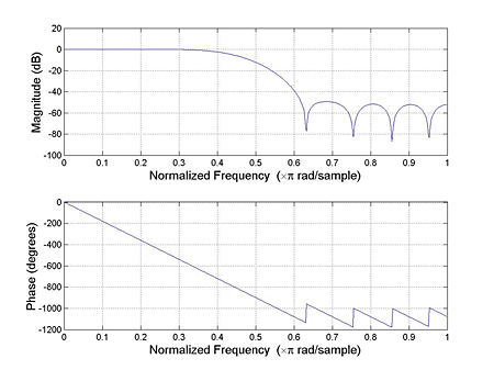
The low-pass filter is shown in Figure 1.

Figure 1: Low-pass filter
The high-pass filter is shown in Figure 2.

Figure 2: High-pass filter
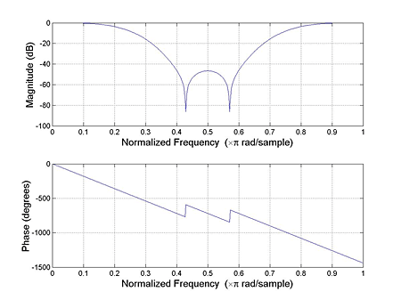
The band-stop filter is shown in Figure 3.

Figure 3: Band-stop filter
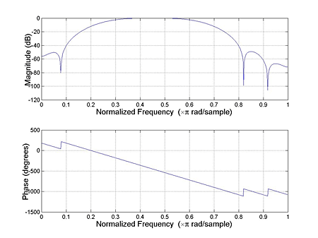
The band-pass filter is shown in Figure 4.

Figure 4: Band-pass filter
Filtering of raw data in Matlab was easily accomplished with the following command:
The filter coefficients initially produced in Matlab were in floating-point decimal format.
They were converted into two's complement, fixed-point format before being stored
in the filter ROM.
|