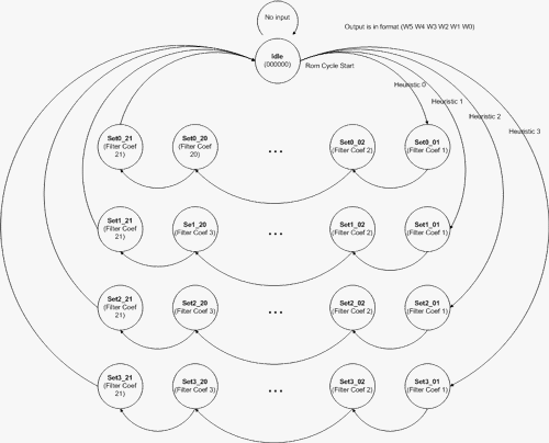
| The FIR filter require a set of coefficients that are stored in a PLA. Each of the 4
filters has 21 independent 6-bit coefficients. The PLA initializes to an idle state,
and upon receiving a cycle start command from the control unit, proceeds to decode the
input
heuristic
pins
(2) and jump to the appropriate filter set. The ROM unit then outputs one filter coefficient
per cycle, which is the same timing needed by the multiply and accumulate unit to calculate
a filtered signal value. Upon competing the output sequence, the PLA returns to the idle
state to wait for the next cycle start input. This entire process is shown in Figure
1. |
Click on the diagram for a full-sized view

Figure 1: ROM State Diagram
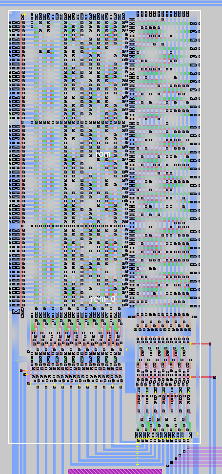
The ROM after implementation in MAGIC is shown in Figure 2.

Figure 2: ROM Unit in Magic
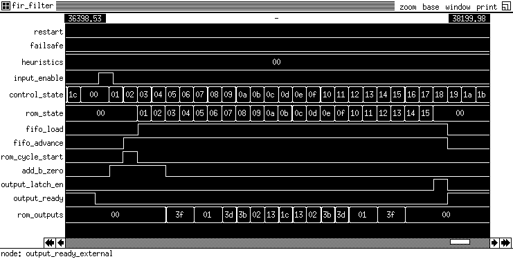
| The ROM and Control Unit PLAs were simulated together in IRSIM to better resolve any
timing dependencies between the two systems. The results shown in Figure 3 clearly show
the control unit starting after the input-enable line is asserted, and cycling through
its state machine as expected. It clears the accumulator and asserts the rom-cycle-start
signal which triggers the ROM to also cycle through its set of stored coefficients as
selected by the heuristics input. The control unit ends by asserting the output-ready
signal. |

Figure 3: Control Unit and ROM PLAs
ROM I/O Signals:
- (I) H0, H1 - Input heuristics to select filter type
- (I) ROM_CYCLE_START - Trigger from control unit to start filter system
- (I) RESTART - Restart PLA
- (O) W0, W1, W2, W3, W4, W5 - Output filter coefficients
See Also: