A 21-element, 10-bit wide circular FIFO was constructed for the FIR filter. The FIFO
holds incoming data samples and cycles through them one at a time. It has 10-bit
input and 10-bit output data lines, as well as load, advance, and clock signals.
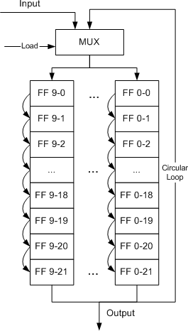
The design of the FIFO is shown in Figure 1. Each block represents a single 1-bit
flip-plop, while each column is a group of 21 sequential flip-flops. There are 10
"columns" in the full FIFO, albeit implemented as rows to make better use
of available chip space as shown in the floorplan.

Figure 1: FIFO Design
When the load signal is low, the input to the FIFO is external to the module. In this
final system, this is connected to the latched input data lines. When load is high,
the FIFO output is looped around to the FIFO input, making it circular.
When the advance signal is high, the data stored in the FIFO is advanced by one stage.
When the advance signal is low, the data remains in the current stage and the output
is constant.
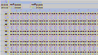
The full implementation of the FIFO is shown in Figure 2.
Click on the figure for a full-sized view 
Figure 2: FIFO Implementation
Detailed implementation views of several FIFO sub-modules are also available:
An IRSIM simulation of the FIFO was performed to verify its functionality. The
results of this simulation are shown in Figure 3.
|