The two critical systems in the FIR filter are the multiplier and adder. Each were
analyzed in Crystal and SPICE to determine their worst-case performance.
16-bit Adder
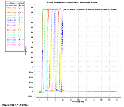
In Crystal, the longest path was found when the adder was given the inputs A=FFFF,
B=0001, and Cin=0. This path of 13.3ns was found along the carry bits of the output,
which ripple from module to module. When this path was simulated in HSPICE, a more
accurate simulator, it was found to be 5.8ns. The SPICE analysis is shown in Figure
1.
Click on the figure for a full-sized view

Figure 1: SPICE analysis of Adder
12-bit Multiplier
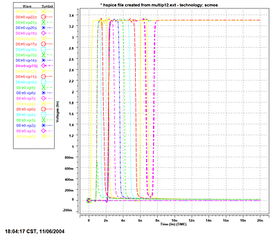
In Crystal, the longest path was found when the multiplier was given the inputs A=FFF
and B=FFF. This path of 17.2ns was along the most-significant bit of the multiply
product. When the same system was simulated in HSPICE, the worst-case path of 7.5ns
was located along the 14th output pin of the product. The SPICE analysis is shown
in Figure 2.
Click on the figure for a full-sized view

Figure 2: SPICE analysis of Multiplier
Overall Performance
The overall performance of the FIR filter is limited by the worst-case speed of the
multiplier, which SPICE simulation placed at 7.5ns. The estimated clock rate of
the final system can be found by taking the inverse of the multiplier latency, and
dividing
it by two, since we are using a two-clock system, and the multiplier should be finished
within half a full cycle. Allowing for a factor of safety of two, the estimated
maximum stable clock speed is 35 MHz.
The filter specifications dictate that data is to be processed at a rate of 44KHz.
This allows 23us for each filter coefficient to be calculated. The 21-tap FIR filter
requires 21 multiplication operations and 20 addition operations to be performed
in that time frame. Given the timing simulations performed above, this process should
be completed within 0.5us, easily meeting the required timing specifications. |